Hawes Amplifier Archive by James T. Hawes, AA9DT
Coupling Capacitors for your FET Amplifier

Skip Intro

Easy Way to Find Coupling Cap Values!

It's Accurate & It's Fast. If you can find a moment's peace, you can even run the calcs in your head! We start with the input capacitor, where we put on the thinking hat. We imaginarily connect the gate resistor RG and the “generator resistance” RIN in series. The generator resistance is the resistance of your previous stage. Or RIN could be the internal resistance of your guitar pickup.

Don't know the generator resistance? Just ignore it for now. We can adjust it later, after we try playing through the amp and see how it sounds.

Rule of Tens

Simplify Your Calculations. The world of coupling capacitors isn't perfect. Manufactured capacitors are only available in certain values. Plus, plain-vanilla capacitor values have tolerances, sometimes wide tolerances. These facts encourage us to build a little leeway into our designs. In fact, our coupler design method defers to the age-old Rule of Tens...

Rule of Tens. A value within 10 percent performs well in most circuits. A calculation within 10 percent is usually accurate enough.
When you figure capacitor values, you depend on impedances and resistors in ohms. Your calculations will go easier if you use round values within 10 percent. The result will remain satisfactory. For example, if you need to know the parallel resistance of a 10K and and 1K resistor, you may skip the calculation! Instead, just use the 1K value. The 1K is close enough to the 909-ohm value that your calculation would crank out.

Input Coupling Capacitor

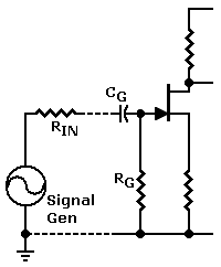
The input impedance is the parallel combination of the signal generator resistance RIN and the input resistor RG. This method assumes that reflected impedances have no effect on the input impedance. (These assumptions apply in typical circuits.) In our example below, the goal is to pass a bottom frequency of 20 Hz. To assure that 20 Hz will pass, we select components for 2 Hz.

CG = 160,000 / [ (RIN + RG) * FLOWEST]
where...
• C is in microfarads.
• F is in Hz.
• Resistors are in Ω.

Example: For (RIN = 10,000), (RG = 1000) & (F = 2 Hz).

  1. Start by adding (10K + 1K) = 11K.

  2. Use the Rule of Tens and round back to 10K.

  3. CG = 160,000 / (10,000 * 2)

  4. CG ≈ (16 / 2) = 8 µF

  5. Use 10 µF (standard value).

Schematic: How to bypass the source resistor with a capacitor. Mouse over to connect capacitor.

Input coupling circuit. (Roll over for simplified view.)

Output Coupling Capacitor

The output impedance is the series combination of the output load and the drain resistor. This method assumes that reflected impedances have no effect on the output impedance. (These assumptions apply in typical circuits.) In our example below, the goal is to pass a bottom frequency of 20 Hz. To assure that 20 Hz will pass, we select components for 2 Hz.

CD = 160,000 / [(RD + RLOAD) * FLOWEST]
where...
• C is in microfarads.
• F is in Hz.
• Resistors are in Ω.

Example: For (RD = 1,000), (RL = 100) & (F = 20 Hz),

  1. Start by adding (1K + 100) = 1.1K.

  2. Use the Rule of Tens and round back to 1K.

  3. CD = 160,000 / (1,000 * 2)

  4. CD ≈ (160 / 2) = 80 µF

  5. Use 100 µF (standard value).

Schematic: How to bypass the source resistor with a capacitor. Mouse over to connect capacitor.

Output coupling circuit. (Roll over for simplified view.)


Capacitor Leakage

CAUTION. Electrolytic capacitors, even new ones, leak current. A FET can detect and amplify this leakage. In some high-impedance circuits (including even regular transistor circuits), an electrolytic capacitor can upset the bias of the input stage. The symptom of this is that the input will load down. Loading affects the achievable swing of the stage. In severe cases, the device will latch to one of the power rails.

The only solution is to swap out the coupling capacitor for a higher quality capacitor. You can expect that the replacement part won't be electrolytic. Just to be sure that you don't have a bad part, try another part of the same type and value. If the symptom persists, use a polyester, polystyrene, teflon or Mylar capacitor. This new choice might force you to increase the lowest input frequency, or change to a new design.


Google Search
Web www.hawestv.com


WARNING. This is your project. Your achievement is entirely yours. I assume no responsibility for your success in using methods on these pages. If you fail, the same is true. I neither make nor imply any warranty. I don't guarantee the accuracy or effectiveness of these methods. Parts, skill and assembly methods vary. So will your results. Proceed at your own risk.

WARNING. Electronic projects can pose hazards. Soldering irons can burn you. Chassis paint and solder are poisons. Even with battery projects, wiring mistakes can start fires. If this page baffles you, this project is too advanced. Try something else. Again, damages, injuries and errors are your responsibility. — The Webmaster


Copyright © 2011 by James T. Hawes. All rights reserved.

•URL: http://www.hawestv.com/mtv_color/colrtel_block.htmWebmaster: James T. Hawes
•Revision—November, 2015 •Page design tools: HTML, Notepad & Explorer