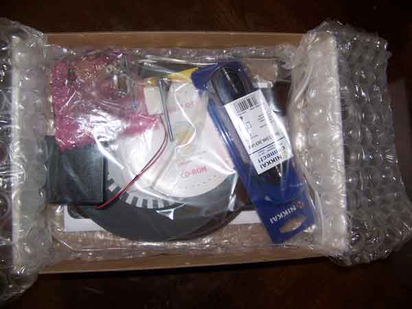
First look inside the kit box
The MUTR Kit
We build it. What if John Baird brought back the Daily Express kit? Unfortunately, at some 120 years old, Baird is pushing up daisies. As far as we know, he's out of the kit business. But MUTR offers the kit!
A few days before Thanksgiving, we ordered our kit from Middlesex University Teaching Resources Limited (MUTR) in Herts, England. Unfortunately, the family budget dictates that delivery by Space Shuttle is out of the picture. Result: The trip across the pond takes a long time. We waited patiently. Our kit finally arrived about a month later, a few days before Christmas.
• Get your kit at: Middlesex University Teaching Resources (MUTR)
Differences from the Peter Smith Circuit
Microcontroller, etc. I note several differences from the NBTVA club circuit by Peter Smith. Among these are the microcontroller, the 324 op amp and the output LED-drive transistor T1. On the NBTV forum, Dominic Beesley points out the purpose of the microcontroller: It's there to provide a test pattern. Baird would have liked this feature. In his day, though, microcontrollers were somewhat rare.
Resonator. To me, part Q1 looks a lot like a ceramic filter. Thanks to Klaas Roberts for identifying the part. Actually it's a ceramic resonator. Part Q1 serves as the clock crystal for the microcontroller.
The 4046 phase-locked loop sync circuit is similar to what the club uses.
| Part | MUTR Kit | Peter Smith |
| Microcontroller | 12F629 | None |
| Resonator* | Q1 | None |
| Op amp 1 | 1/2 of LM324N | CA3240 |
| Op amp 2 | 1/4 of LM324N | CA3140 |
| LED Driver, T1 | BC548 (BJT) | IRF510 (FET) |
| Input follower | None | 2N3702 (BJT) |
*Frequency = (400 Hz * X) ? (Maybe 4 MHz)
Kit Parts
Resistors
Note: All quarter-watt resistors.
| Resistor Table | |||||||||
| R01—7.5M | R06—1K | R11—20K | R16—22K | R21—10K pot | |||||
| R02—10K | R07—10K pot | R12—1K | R17—22K | R22—2.2K | |||||
| R03—10K | R08—180 Ω | R13—100K | R18—100K | ||||||
| R04—30K | R09—390Ω | R14—220K | R19—100K | ||||||
| R05—1K | R10—100Ω | R15—220Ω | R20—4.7K | ||||||
Capacitors
| Capacitor Table | |||||||||
| C01—0.1μF, J / 63V, ceramic | C03—0.1μF, J / 63V, ceramic | C05—22µF, electrolytic | |||||||
| C02—100µF, electrolytic | C04—0.1μF, J / 63V, ceramic | C06—0.1μF, J / 63V, ceramic | |||||||
Main PC Board
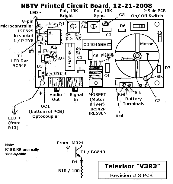
My rough sketch of the PC board (top view) appears below. When time allows, I'll post a better sketch.
Semiconductors
| Semiconductor Table | |||||||||
| PLL: 4046, 14-pin | Quad Op Amp: LM324, 14-pin | PIC: 16F629, 8-pin | |||||||
| T1, NPN Transistor: BC589 (LED drive) | MOSFET: IR542P / IRL530N (Motor drive) | Opto: Might be Optek OPB710 | |||||||
Sync Problems
On my first attempt, I didn't get the sync working. The raster lights, and I see a flipping image. Obviously the sync doesn't work. No adjustment of the brightness and sync pots improved the situation. From reading the forum page on the scanner, I discovered related chronic problems. First, the disc is some sort of floppy plastic material instead of aluminum. I suspect that the disc is that Darvic® (PVC) plastic type that the NBTV club used to sell. My disc is warped. Because the scanner body is open, you can accidentally touch and slow the disc. That's too bad. Holding the scanner peephole up to your eye is the easiest way to see adjustments.
Here are some another forum discussions of the kit...
Kit Forum 3 (incl. Phonovision)
A second sync-related problem is that the distance between the opto sensor and the strobe disc is variable. You must guess how close to get the opto. Supposedly you should get the opto as close as possible. But the disc wiggles. It might be too close at one time and too far at another. Also, if you get the disc too close, the opto will slice through the strobe disc. The printing is only a laser print. Toner smears and powders off rather easily. One forum member is already trying to repair his strobe disc.
Infrared opto. Another guy mentions that the infrared opto responds to ambient light from the nearby screen illumination LED. He made a shield. I intend to try a shield, too. We sometimes eat prepared dinners, and they come in nice plastic containers. Maybe I can make a shield out of a piece of this plastic.
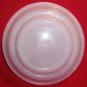
Better DiffuserSource. I'm also looking for a replacement diffuser. I think that I've found another container that will provide suitable plastic. See Healthy Choice Cafe Steamers. Unwanted texture. Like the side of some milk containers, the original diffuser has a stippled surface. The stipples degrade picture resolution. I've seen this problem before. My scratch-built scanner uses real ground glass from American Science & Surplus. Another place to look for a good piece of ground glass is Surplus Shed. Edmund Scientific (now Anchor) used to deal with amateurs, but the current prices indicate that those days are over. I also don't see as many surplus items at Edmund and Anchor. |
|
Suggested Improvements
|
|
|
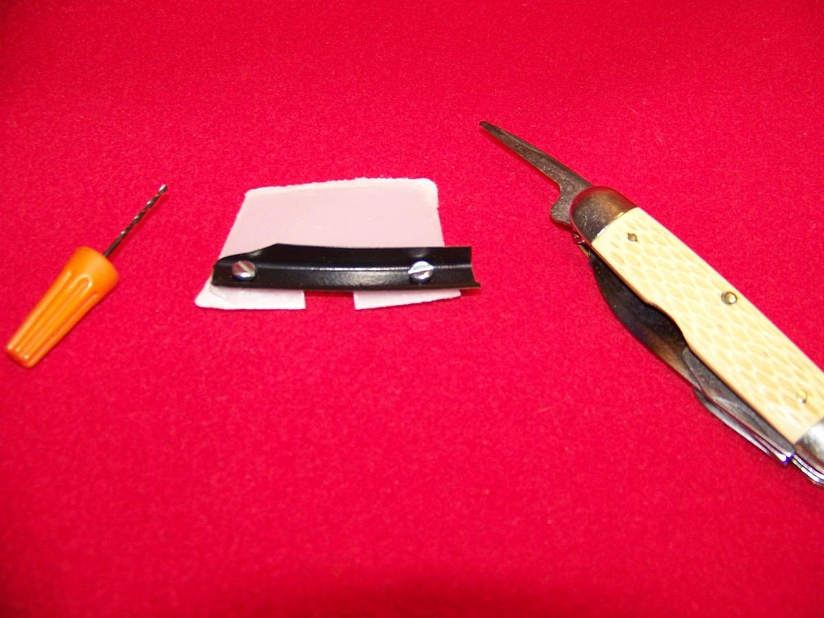
The black, plastic "light fence" that I cut from a prepared dinner tray. |
|
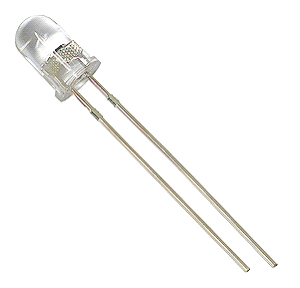
A white, super LED of the type that I soldered into the circuit. |
Test Patterns
See... Test Patterns from Klaas Robers, PK0KLS.
