Two-Color TV History
Two-color TV, highlights. In television, two-color reproduction has a long history. Here are some highlights...
|
Gould 3D. In 1932, Leslie Gould patented a two-color, three-dimensional television system. This system reproduced a 360-degree view of an enclosed, finite space. The effect was something like viewing a moving Mercator projection, including naturalistic contours. The system wasn't anaglyphic, and didn't require viewing glasses. [Gou., Figs. 1 & 4] See the Gould 3D patent drawing, right. Items (231) are the orange-red and teal lamp tubes. A revolving arm (215) carried these tubes as it rotated behind the scanning drum (219). The drum and arm rotated in opposite directions. The Gould TV drum (219) was cylindrical. The viewer could watch a realistic image from the front, back or sides of this TV! A translucent screen outside the drum was optional. |

Gould's 3-D, two-color monitor. Drum #219 offers a 360°, cylindrical viewing area! |
|
Alexanderson. Ernst Alexanderson invented a two-color, NTSC-compatible TV system in 1940. This system used a color wheel that rotated before the CRT at 1,800 rpm. [Abr., 266-267] In 1933, Alexanderson had patented a two-color television system that used two CRTs in the receiver: Each with a complementary color filter. [Ale.] If CBS had adopted either Alexanderson system, the company could have avoided its monochrome-compatibility problems. Alexanderson's systems would have accurately reproduced flesh tones. The flicker would have been minimal. |

Alexanderson
|

Camarena
|
Camarena. In 1963, Guillermo GonzŠlez Camarena demonstrated his version of two-color, field-sequential NTSC. He proved his system in broadcasts from Mexican station XHGC. Camarena's system could use either a color wheel or a color CRT display. In either case, the electronics were vastly simpler than those for NTSC color. The standard vertical sync signal triggered color field changes. [Sol., 48, 71] |
|
|
|
NRI Schools. For decades, NRI Schools® (National Radio Institute) offered superb correspondence courses in electronics. Budding technicians performed lab experiments on the famous Conar® kits and prototyping stations. Most of the test equipment also bore the dependable Conar brand. In the late 1960s, one NRI course may have included a two-color color wheel TV kit. (At the Antique Radios.com forum, the author has read about such a kit.) The kit would have been an NTSC-compatible color receiver. It would have included a phase selector, a demodulator, and a synchronized color wheel. Keep your eyes open. This very rare kit might just turn up on eBay!
Two-color NTSC
Col-R-Tel® in Two Colors
With only a few modifications, cyan and red Col-R-Tel seems quite possible. A two-color set would have far less flicker than does the three-color model. Yet the two-color version would still render flesh tones (the most important colors) perfectly. Eliminating flicker is a significant upgrade. Most viewers would appreciate the modification.
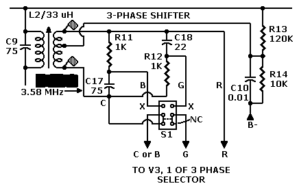
Change summary. First, the color wheel changes: We must replace the six-segment, RBG—RBG color disc. The new disc also has six segments, but the six color wedges alternate between red and cyan (or orange and teal). The electronic changes might not be any more difficult than a Col-R-Tel installation. The main change is the addition of a two-pole, double-throw switch. Here's the step-by-step approach...
Assembly Procedure
After examining of the Col-R-Tel schematic and operating instructions, the author pieced together the modification procedure below. [Col., 3, 7 & 8]
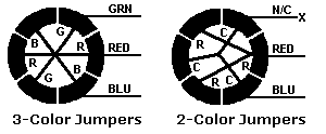
- Replace the three-color, six-segment disc with a two-color, six-segment disc.
- Connect a wire to the cyan (-R-Y) tab on phasing coil L2.
- Cut the blue and green (B-Y and G-Y) lines between coil L2 and V3. (On the drawing, points with the marking "X.") From now on, we'll call the transformer side of the cut the "input wire." We'll call the V3 side of the cut the "output wire."
- In a convenient location near the cut wires, mount DPDT switch S1. In later steps, you'll wire the switch in series with the blue and green color-phase lines from phase coil L2. When wiring the switch, you might need to add wire. To avoid noise, keep the wiring as short and direct as possible.
- To the bottom-left tab, connect the -R-Y signal input wire. The -R-Y signal is an inverted red signal that comes from the bottom transformer phase. Another name for inverted red is cyan.
- Leave the the bottom-right tab open.
- With a picture on the screen, adjust your TV for the sharpest picture. Use these controls...
- With a picture on the screen, adjust the Col-R-Tel hue and saturation controls: (The chassis labels identify these controls as Color Lock and Color Gain.) Continue adjusting until you achieve the best possible flesh tones.
| • Fine Tuning: For sharpest picture | |
| • Contrast: Increase | • Brightness: Increase |
Bibliography
https://is.gd/EETJ79
(Access on February 22, 2022.) •Re: Superb, well-balanced international history of television technology, by author with engineering background. This first volume traces television development from its nineteenth century roots to beginning of World War II. Second volume extends story to 2000, with special emphasis on videotape. These books read more like database than narrative. Extensive second book loses some luster, but is nonetheless valuable reference.
https://patents.google.com/patent/US1988931A/en
(Access on February 23, 2022.) •Re: U.S. patent for Alexanderson's two-color television camera and monitor. Of particular interest: Figs. 1 & 4.
https://www.earlytelevision.org/pdf/colortel_manual.pdf
(Access on January 30, 2022.) •Re: Manual for Col-R-Tel, 1955 predecessor of Spectrac & Scope. Col-R-Tel could reproduce 3 primary colors. Schematic in manual details switch connections that require modification for two-color operation.
https://patents.google.com/patent/US2058681A/en?oq=U.S.+patent+2%2c058%2c681
(Access on January 30, 2022.) •Re: U.S. patent for Gould's 3D, two-color television camera and monitor.
(Access on February 2, 2022.) •Re: Description of Camarena's color television system using two primary colors. Successful tests over station XHGC in Mexico.
Go to Page: 1 2 3 4 5 6 7 8 9 Next
Page Directory
On this page...Two-Color TV History 2-color NTSC 2-color Col-R-Tel Assembly Schematic
On related pages...
What is Two-Color TV? Col-R-Tel vs. Spectrac TV System Flicker Comparison 2.5-Color TV Gould Television: 3D from the Great Depression Gould 3D: Could It Work? Gould 3D: Camera & Monitor Formulas The Lost Creations of Leslie Gould Spectrac: Color for a Monochrome World


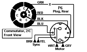
 Commutator Jumper Diagram
 Col-R-Tel 2-Color Commutator Wiring (Mouse over for 3-color wiring.)