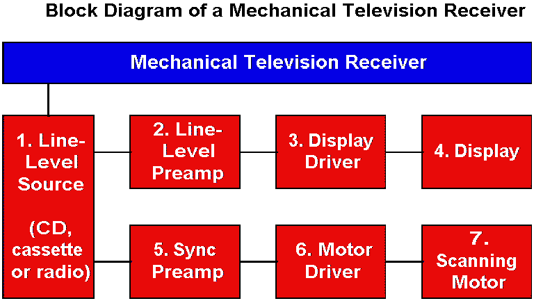
About Mechanical Television Receiver Blocks
- The Line-Level Source provides the input signal from the audio-frequency source. The source can be a preamplified radio, tape, CD output, etc. These devices can put out a volt
or more of signal. Smaller input signals require more extensive line preamplifiers. Voltage gain
is a maximum of 30 times per stage. Typically, the output level is at least in the millivolt range.
|

|
- The Line-Level Preamp accepts the input signal (sine wave) from an audio-frequency source.
Bandwidth varies. Pictures with a small number of lines (24) need only a narrow band of
frequencies. Pictures with a large number of lines (60 and up) need a broad band that extends into the
ultrasonic frequencies. The line-level preamp is a class-A voltage amplifier. This amplifier provides an
appropriate level for the display driver. From peak to peak, the AC input signal amplitude might be
700 millivolts to about a volt. From the CD player speaker, the necessary preamplifier is usually
only one stage (one transistor). From the source's line output, the necessary preamplifier is two to
three stages. A simple Darlington preamplifier often works splendidly.
- The Display Driver accepts the output signal from the line-level preamplifier. The display
driver provides sufficient current to drive the display. The driver stage is a power amplifier. The DC
restorer (if necessary) will be at or very near the driver stage. The same goes for the optional
gamma corrector. (The DC restorer allows large detail to display in its natural contrast range. This
circuit reverses pictorial damage from AC coupling. The gamma corrector alters the brightness
contour or slope.) With LEDs, the driver usually direct-couples to the display. The driver should
probably include some sort of current-limiting circuit. Except in the simplest applications, a
current limiter protects the driver and display from shorts.
- The Display. Original displays were neon glow tubes, crater neon tubes, or modulated
arcs. Experiments with color mechanical TV added other types of glow lamps. (For instance,
mercury vapor and argon.) Some displays used light valves with rear illumination from incandescent
or arc sources. (With laser illumination, we still use light valves today.) Today, hobbyists use super
LEDs and direct-drive them with transistors, Darlingtons or MOSFETs. The display driver amplifier
can drive LEDs in only one phase: That is, the driver turns on, or turns off the display.
Biphase displays are possible, but only with multiple LED colors. (Otherwise dark
and light picture areas would cancel. That is, they'd appear equally bright.) Like normal diodes, the
LEDs rectify. That's why LED displays only use one phase of the amplified video signal. To use more
of the signal, a designer can apply DC bias to the LED. The bias voltage turns the LED on halfway.
With zero signal, then, the LED produces a mid-gray tone. The video signal then adds to or subtracts
from the bias voltage. Adding produces white, while subtracting produces black. (The same technique
works for other nonlinear displays, such as neon tubes and CRTs.) The display driver amplifier can
operate in series or in shunt with the display.
- The Sync Preamp. The sync photosensor output level is fairly high. (Volts: The photosensor has
an LED shining straight at it.) The sync preamp amplifies and limits (clips) this level. The sync preamp also
builds up the power (current) of the photosensor signal. The output is strong enough to operate
the motor driver.
- The Motor Driver. With sufficient current from the sync preamp, the motor driver turns on
all the way. The motor then operates at full speed. At this speed, a lagging disc soon comes into sync
with the transmitter disc. When the transmitter and receiver discs are in sync, the motor driver receives
medium current. This current maintains the present speed. If the receiver disc is fast, the motor
driver receives low or no current. The motor soon slows down to sync speed.
- The Scanning Motor typically turns at synchronous speed. In the MTV era, usual speeds
were 12.5, 15 or 20 frames per second Mfps. Today, mechanical TV devices such as micromirrors
can scan much faster (180 fps). Engineers tried slower and faster speeds. Slower speeds
didn't allow the eye to fuse the image. (Fusion requires about 15 fps.) The viewer perceives flicker or
even lines scanning across, as with slow-scan television (SSTV). Flicker reduction requires
48 fps or a greater speed.
- The Scanning Disc (not in diagram) varies in size. Disc diameter varies
according to picture dimensions and picture resolution. The number of disc holes determines
picture resolution. Disc-based pictures are wedge-shaped. For a roughly square picture, the
disc diameter is roughly this wide: [(Picture width • number of holes) / 2].
Click...
More about how mechanical TV works
Go to Page:
1
2
3
4
Back
|
On this page
|
