|
|
ASSEMBLY
- When you build the circuit, wire it up except for the resistor between the transistor Q1
base and Vcc (10K on the schematic).
- A 10K resistor works fine in my circuit, but may not work with all transistors.
- Clip in a 10K resistor and check the circuit performance with the CD audio.
- If the contrast range is good, then solder in the 10K resistor.
- If the LEDs tend to remain dim or bright, but don't vary much, try a resistor that's
close in value to 10K.
- Some other resistors that might work are 4.7K, 5.6K, 6.8K, 7.5K, 12K, 15K or 22K. Try
each of these resistors in sequence and retest after you clip each one into the circuit.
- One value should work much better than the others do.
- Also, during the test, be sure to run the CD volume control through its range. I expect
the best resistor value to perform optimally with the volume control between its midpoint
and all the way down.
OPERATION
- When you're ready to use the LED driver, make sure that the left channel of your CD player
outputs inverted video. If the CD player outputs positive video, either flip the driver's
input leads or use an inverter. (The inverter goes between the CD output and the LED driver.)
If you don't know which type video your CD outputs, skip this step. When you begin watching
pictures, you'll either see a positive or a negative image. If you see a negative image, you
have a CD player with positive video. For a positive (normal-looking) picture, flip
the input leads.
- Scan the display with a Nipkow disc or other means.
- If the CD player features an isolated phone output: Connect the display circuit
directly to the CD player.
- If you don't know what type output your CD player has: Use a 1uF isolating
capacitor. Remember that any capacitor adds visible phase shift artifacts to
your images. A capacitor causes average gray values to vary in brightness.
Depending on the scene, background objects tend to dim or brighten. (This
problem is the reason for a DC corrector circuit.) An electrolytic capacitor introduces
leakage that changes the stage bias and affects all gray values. In high-impedance
amplifiers, the leakage can be great enough to block the signal. Avoid
electrolytic coupling capacitors!
- Set the CD volume control. You should now have usable video.
- Sync up the picture by your own means.
|
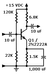
Conventional inverting preamp with gain. (Parts values for reference only.)
No-gain preamp with phase splitter. Switch allows you to choose inverted or
non-inverted video. (Parts values for reference only.)
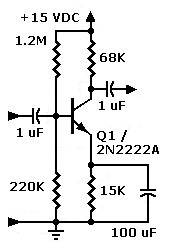
High-impedance inverting preamp with gain. (Parts values for reference only.)
|
|
CIRCUIT PHOTOS
|
Right: Front view of the Radio Shack 276-150 PCB. Note the small, PNP
voltage preamp below the Darlington device. The ground connection is on the top
of the PCB. Vcc connects to the rings on the bottom of the board.
Note: A plain perfboard would have probably worked better than this board did, but the
size is about right. If you want to add a phase inverter, you'll need another half inch or
so of PCB.
|
|
|
Right: Back view of 276-150 PCB. LED matrix wiring is on
the top. The driver electronics are on the bottom. Between the display and
drive electronics, I cut the board's ground and Vcc buses. I then substituted
my own ground bus across the top of the PCB. The Vcc bus runs across
the bottom of the PCB.
|
|
Go to Page:
1
2
3
4
Next
|
|